ABOUT ENGINES
This page is created as a timeline, starting with the steam engine, moving on to industrial machinery, where our milk centrifuge was of particular importance to us and Danish agriculture, then moving on to the era of the diesel engine. We will then look at how other types of engines work, including the internal combustion engine, running on petrol the electric engine and finishing off, by taking us to todays day and age, explaining Power 2X.
Hvis du som underviser savner specifict indhold, hører vi meget gerne fra dig på dieselhouse@everllence.com
Happy reading!

ABOUT STEAM-ENGINES IN GENERAL
In the 18th century, Scotsman, James Watt, developed the steam engine and it was immediately a technological revolution. Hard work no longer had to be done by humans and animals. In the 19th century, industrialization really took hold in several countries and the steam engine had it's heyday. Steam engines would power trains and ships, as well as an increasing number of factories.
HOW STEAM-ENGINES WORK
Steam engines are heat powered engines that convert part of the thermal energy in water vapor into mechanical energy. In steam engines, heat is transferred at a high temperature through water, which creates steam in a boiler. The steam is led into the engine, where it expands and causes movement to the engine's mobile parts. The efficiency of the steam engine depends on how much heat is supplied and how efficiently the heat is used.
HISTORY
Newcomen's piston steam engine
The first piston steam engine was first built by Englishman Thomas Newcomen in 1712. It worked with a steam pressure only slightly higher than the atmospheric pressure and consisted of a piston connected to a pump rod with chains mounted on a rocker boom. The steam was admitted into the cylinder below the piston, which was raised to the top position with the help of a counterweight on the pump rod. Cold water was then injected into the cylinder, thereby condensing the steam and creating a vacuum, so that the pressure pushed the piston down and thus pulled the pump rod into the air. Newcomen's engine initially had only limited usefulness and low efficiency, but it rested on reliable technology, which was later further developed. During the 1700s over 1000 "atmospheric" steam engines of the Newcomen type were built.
James Watt's improvements
A great weakness in Newcomen's engine was an enormous loss of energy due to the constant alternation between heating with steam and cooling with water. This problem was solved by James Watt in the mid-1760s. In 1769 he obtained the patent for his separate condenser, which meant that the cylinder could be kept warm constantly. Instead of injecting cooling water into the cylinder, condensation took place in a separate container, the condenser, which was connected to the cylinder.
In the 1780s, Watt added a number of new inventions that made the steam engine more useful and efficient. He obtained a patent for a power transmission through a gear-wheel construction, which could convert the up and down movement of the piston into rotation, and for a construction where the steam could act with it's pressure on both the up and low of the piston's movement. The steam engine thus became double-acting in contrast to the previous single-acting machines. Furthermore, he constructed the so-called parallelogram, which could replace the previously used chains with a rigid connection, so that the piston both pressed and pulled on the rocker arm.
“I had once adjusted the machine so that it made less of a spectacle. But the owner could not sleep when he did not hear it raging. People seem recognize the machine's power by it's noise. Modest skills are apparently recognized neither in humans nor in machines".” At first, the noise of the steam engine was associated with efficiency. Quote: James Watt (1736-1819).
From steam to diesel
However, the steam engine had a large energy loss. For this reason, German engineer, Rudolf Diesel, sets out to achieve better energy utilization, as he in the 1980s began the development of what in the 20th century became known as the diesel engine.
The work of keeping the steam up in the boilers was hard and tiring work. On the ships, many seamen were retrained as engine-men as the coal-fired steamships were replaced by diesel ships around the 1920.
Today, the piston steam engine has outplayed it's role. But today, steam power is still used in turbines, which via paddle-wheels drive a shaft with several thousand revolutions per minute. The technology is particularly suitable for producing electricity and steam turbines are the primary power source at the large electricity plants, e.g. at the H.C. Ørsted power plant.
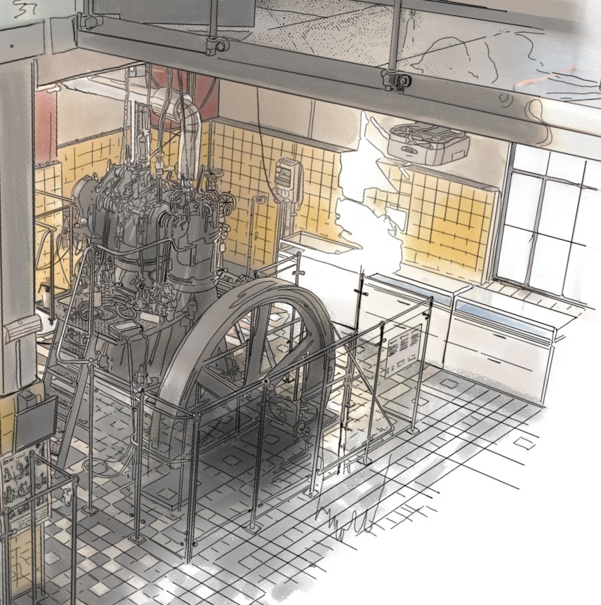
STEAM ENGINE NO. 162
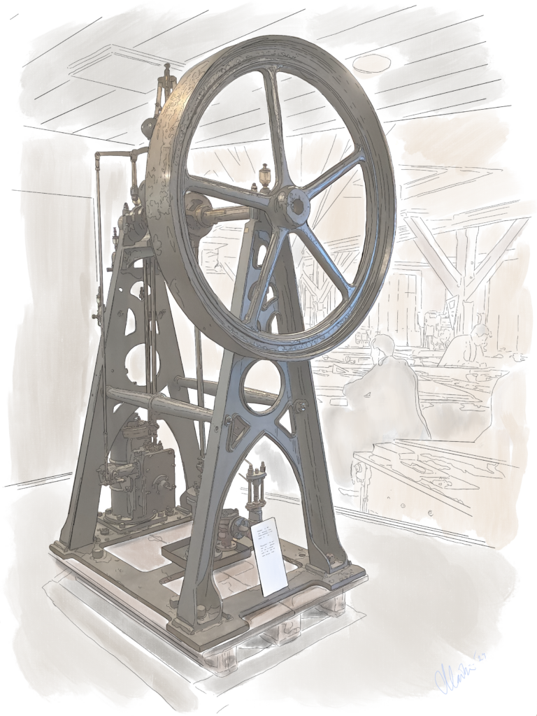
Steam engine no. 162 from the Baumgarten & Burmeister's establishment was delivered in 1859 to the Gunpowder Mill in Frederiksværk. The machine can produce 2 hp.
The original steam engine No. 162 is on display at the museum.
S/S HJEJLEN

S/S Hjejlen was built by Baumgarten and Burmeister in 1861 and in addition to being Denmark's oldest sailing steamship, it is also the world's oldest coal-fired paddle steamer.
Hjejle is the Danish name for the bird Golden Plover. The S/S Hjejlen still sails on the Silkeborg lakes and if you sail along with it, you can still experience the shoveling of coal under the boiler, as has been the case for 150 years. The ship continues to get propulsion from the original steam engine.
S/S Hjejlen's story
In 1844 a paper factory was founded by the stream Gudenåen and in 1857 Silkeborg got its own newspaper. In this, the editor planted the idea of a steamship for transport and tourism between Silkeborg and Ry, whom did not have a railway at the time.
In 1859, the citizens of Silkeborg, led by the paper factory's founder, Michael Drewsen, began to draw up shares for the project. The goal was to generate 8,000 reigsdaler, but when only 3,000 were gathered, Drewsen chose to order a ship for 10,000 reigsdaler anyway, with a loan from the Danish state of 5000. That the loan became an opportunity is largely due to a close acquaintance with Countess Danner and Frederik the Seventh.
S/S Hjejlen has benefited the people of Silkeborg for 150 years.
ENGINE FACTS - S/S HJEJLEN
Build no.: 15
Client: Hjejlen Aps, Silkeborg
Type: B&B højtryksdampmaskine
Length: 25 meter
Width: 3,6 meter
Dept: 1,7 meter
Load capacity: 6,5 tdw
Speed: 8 knots
Scale of museum model: 1:96
In the DieselHouse you can experience a model of S/S Hjejlen.
THE FRIGATE JUTLAND
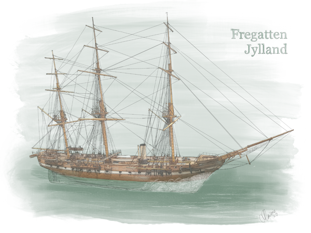
Frigate: a fully rigged three-masted ship.
Fuldrigget: rigget med råsejl, tre sejl per mast, siddende på undermast, mærsstang og bram- og røjlstang.
The frigate Jutland was the last fully rigged ship in the Danish fleet and is today the world's longest preserved warship built of wood. The frigate was built at Orlogsværket in Copenhagen and was equipped with a B&B steam engine.
History
In 1860, the frigate Jutland was completed as a warship, with room for a crew of 437 men.
The frigate Jutland is a full-power frigate, which is characterized by being built of wood and having masts, but was also equipped with an engine and a screw that made it possible to sail both for wind and coal power.
The frigate Jutland was built in the middle of Denmark's industrialization, in a society in a rapid development. It was the first ship in Denmark that could sail at full steam, but due to the amount of coal that had to be used, it was also useful to be able to sail at full sail when the wind allowed it. It was the hallmark of the frigate Jylland and with its top speed of 14 knots, Jutland was also the fleet's fastest vessel in 1964, documented in a race off the coast of the Danish island of Møn.
In 1864, the frigate took part in its only war, when Denmark fought over Schleswig, Holstein and Lauenburg during the Second Schleswigean War. Denmark suffered one defeat after another, but on May 9th, in the Battle of Helgoland, the frigate Jutland, the frigate Niels Juel and the corvette Heimdal put the Austro-Prussian enemies to flight, after heavy shelling both ways for two hours. 12 men lost their lives and 35 were seriously injured on the Frigate Jutland.
In 1874, King Christian IX went north on board Jutland, in the 1000th year of Iceland's settlement, to hand the Icelanders their first constitution. King Christian IX also sailed to the Faroe Islands and Russia with Jutland and in the years 1871-1887 the frigate visited the Danish West Indies, as it was then called, and the Mediterranean. In 1876, the frigate Jutland ceased to be a royal ship and in 1887-1909 became a barracks ship.
In 1908, the navy decided to sell the frigate to be scrapped, but a group of naval officers and merchants did not want to accept this faith for the frigate and bought the ship with own funds, thus preventing the frigate's final disposal.
During the First World War, the frigate served as a telegraph station in Nørresundby, in the southeren Denmark, and at the same time housed the battalion that stood guard at the pontoon bridge over the Limfjord.
The owners of the ship tried for years in vain to raise money for the frigate's maintenance, but eventually had to sell to landowner Schou from Palsgaard, who anchored the frigate north of Juelsminde in Jutland in the western part of Denmark, where it again functioned as a telegraph station until 1925.
In 1934, Prime Minister Thorvald Stauning joined the fight to preserve the frigate. Stauning allowed the preservation of the frigate to be included in an employment project for the unemployed during the crisis.
Over the years of 1936-1949, the Frigate Jutland housed 200,000 children through the project "The association for provincial children's care in Copenhagen" which gave provincial children a place to stay on their school trip to Copenhagen. This project as a thank you for the provinces taking in the children of the cities during the holidays, during the great cholera epidemic in 1853.
On the 2. of December 1947, the frigate Jutland sank in the Copenhagen harbor due to a sea valve that was not properly closed. The frigate was immediately raised.
Due to a lack of maintenance, it was decided in 1960 that the frigate could no longer house the country's children, but instead had to be renovated and included as a tourist attraction in Ebeltoft, in Jutland in the west of Denmark.
After struggling for years to raise money for the restoration, the A.P. Møller Foundation in 1989 donated the necessary money for the extensive renovation.
In 1994, the gangway could be opened for visitors for the first time Museum The Frigate Jutland
In DieselHouse, we have a large model of the Frigate Jutland, as well as a model of the ship's guns, made of the original wood, taken out of the frigate during the renovation. We also exhibit cannonballs, found in 1872-73 during the construction of the B&W shipyard, as some of the small islets in the north-eastern part of Copenhagen Harbor were filled up. The cannonballs are believed to originate from the Swedes' attack on Copenhagen in 1658.
ENGINE FACTS - THE FRIGATE JUTLAND
Build: 1857-1862
Delivered 1860
Owner: The Danish Marine
Length over bows: 71 m
Width: 13,2 m
Max hight of masts: 53 meter
Dept: 6 m
Load capacity: 2.456 tdw
Engines: 2-cylinder horizontal B&B low-pressure steam engine
(was taken out of the frigate around 1892)
Horse powers: 400
Coal consumption per hour: Approx. 1.8 tonnes of coal. 247 tonnes of coal reached full steam for approx. 137 hours.
Performance: 1300 hp
Top speed for sail: 15 knots
Top speed on steam: 11 knots
Build price: 784.299 rigsdaler
Number of canons 44 (in 1864)
Hull made of: Oak
Scale of museum model: 1:96
STEAM ENGINE NO. 356

Steam engines played a major role in the expansion, excavation and deepening of Copenhagen's harbor facilities towards the end of the 19th century.
In 1843, H. H. Baumgarten started a mechanical workshop in Købmagergade in Copenhagen. In 1846 he went into a partnership with C.C. Burmeister and formed the company Baumgarten & Burmeister. The same time, the workshop had to move to Christianshavn due to space constraints. As early as 1847, they produced the first steam engine that was sold to chocolate manufacturer Aagaard in Copenhagen.
W. Wain, worked closely with the two at the Orlogs shipyard and when Baumgarten retired in 1865 Burmeister & Wain (B&W) was formed.
The B&W steam engine No. 356, was used on floating cranes owned by the Copenhagen Port Authority and was in use until the 1930s.
ENGINE FACTS - B&W STEAMENGINE NO. 356
Delivered: 1872
Cylinders: 2
Performance: 40 hp
FRITZ JUEL STEAM FERRY
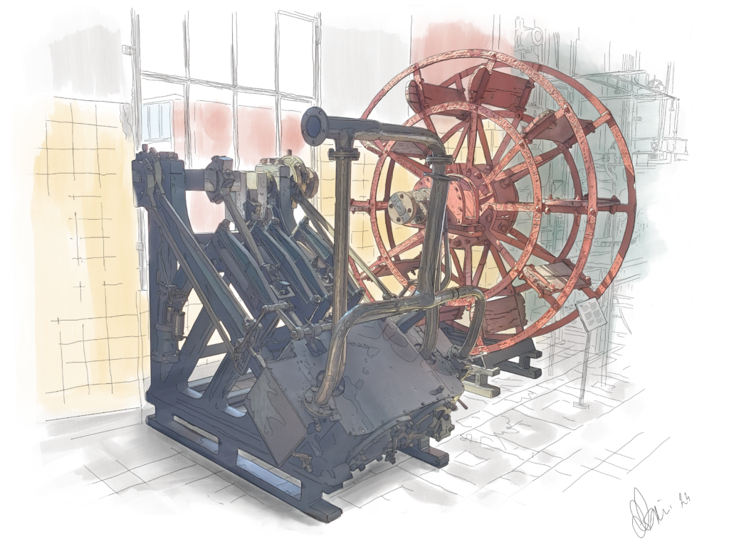
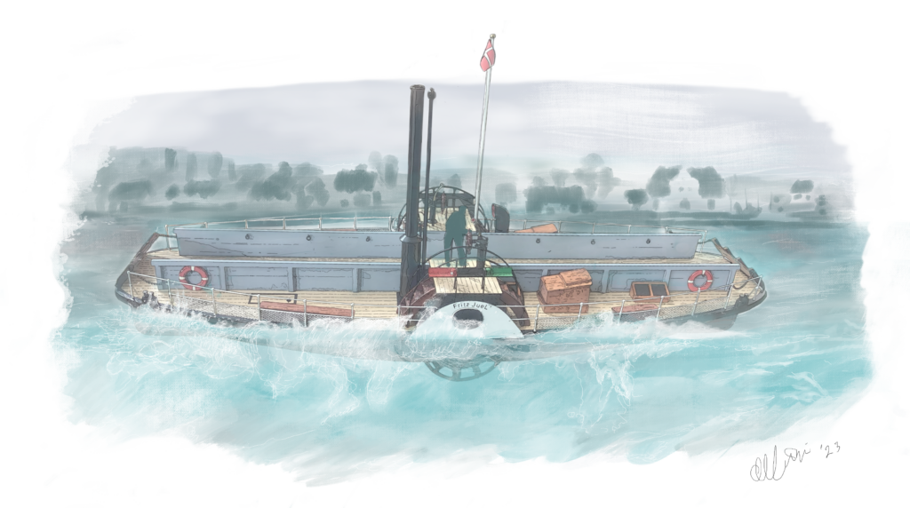
The steam passenger ferry, Fritz Juel, was built by Burmeister & Wain and delivered to Svendborg County in 1873. The ship was Denmark's first car ferry and used to sail between Svendborg and Tåsinge.
The ship was last in service during World War II until 1946.
The museum displays the original high-pressure steam engine from Fritz Juel, as well as one of the ship's two original paddle wheels.
The museum will eventually be able to demonstrate a steam engine in use.

ENGINE FACTS - FRITZ JUEL STEAM FERRY
Delivered: 1873
New built no.: 76.
Ship weight: 18 tonnes (37 brutto tonnes)
Top speed: 5.5 knots
Maximum performance: 50 hp
D/H DANNEBROG
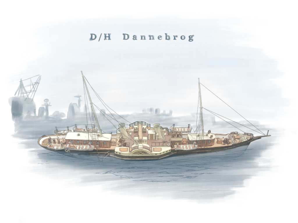
The paddle steamer D/H Dannebrog was designed and constructed by Orlogsværftet as a royal ship and functioned as such until the current royal ship, also named Dannebrog, was delivered in 1932. D/H Dannebrog was a royal ship under King Christian IX, Frederik VIII and Christian X and served as a royal ship for 53 years, from 1879-1932 and was built by B&W. In 1934, D/H Dannebrog was broken up. At DieselHouse you can experience a model of D/H Dannebrog.
ENGINE FACTS – D/H DANNEBROG
Build: 1880
Build no.: 109
Owner: The Danish Navy Ministry (The Danish Royal Family)
Load capacity: 180 tdw
Engines: Two B&W high- and low pressure steam engines
Performance: 1200 hp
INDUSTRIAL MACHINES
In 1846, Baumgarten & Burmeister produces a wide range of industrial machines, such as printing presses, drying machines, dye mills, etc.
KNIPPELS BRIDGE
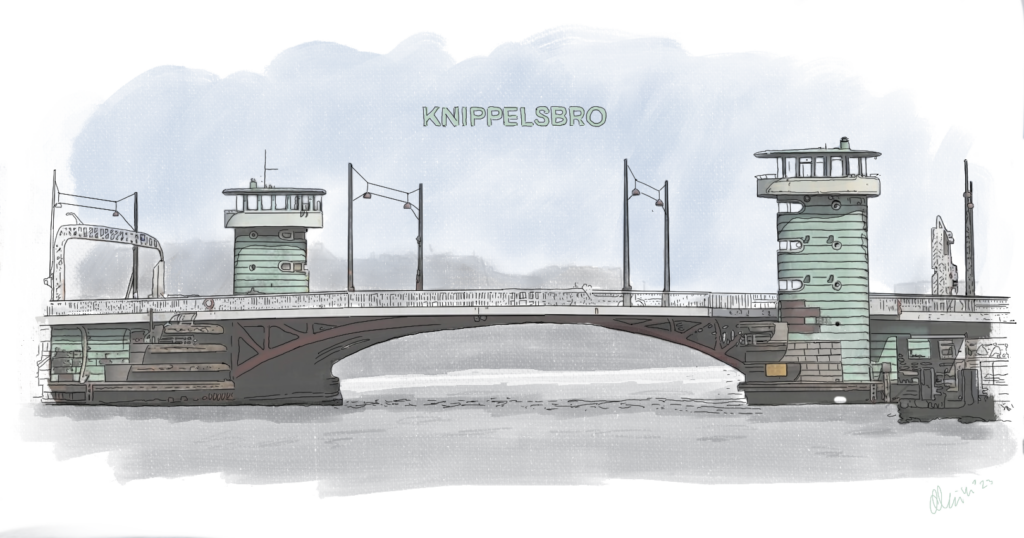
Knippelsbro (Knippels Bridge) stands as one of Copenhagen's best-known landmarks and is also the oldest preserved bridge connection in the Port of Copenhagen. But did you know that B&W was involved in the making of the bridge?
1868-69 Burmeister & Wain built a new bridge to replace the old Knippelsbro. It was an iron bridge, designed by wholesellers J. Adolphs and C. A. Broberg.
The bridge connected Slotsholmsgade with Torvegade and was built next to the old bridge, which was used during construction. The bridge opened on August 1st, 1869.
1934-37 the bridge had to be renewed again and Burmeister & Wain was once again given the honor of being responsible for the construction work, together with the contractor company Wright, Thomsen & Kier. Harbor builder Godfred Lorentz was responsible for the construction and architect Kaj Gottlob for the design. This was when the two well-known copper-clad bridge towers was constructed.
While undergoing the work, a temporary bridge was established next to it.
The new Knippelsbro was inaugurated on the 17th of December 1937 and appeared as the bridge we know today, only thoroughly renovated in 1989 with respect for the architecture.
The bridge engine was of course supplied by B&W.
HISTORY
Historically, Knippelsbro goes back much further: In 1618-20, Christian IV had the first bridge built, which was later to be named Knippelsbro. The bridge went over the harbor channel when Christianshavn was built. The district was to function as a defense against enemies coming from the sea side.
In 1633, Hans Knip became a keeper at the bridge and collected tolls from the passing ships. The bridge was originally called Christianshavn's Bro, but was popularly called Knippen's Bro, which over time became Knippelsbro.
During the bridge's time, there have been a total of five bridges, which have looked radically different, starting as a wooden bridge with statue entrances, then with entrances with wooden carvings, then B&W's iron replacement, next came a bridge with gates with bridge houses on top of them, before finally setteling on the 1937 B&W bridge we know today.
At DieselHouse, the original drawings are shown as well as the 1937 model showing the lifting mechanism.
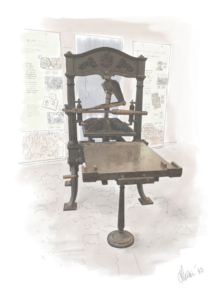
PRINTING PRESS NO. 15
Constructed by Baumgarten & Burmeister in 1847.
April 1st 1851, the first Danish stamp was released. The stamp was printed on a printing press of the same type as the one displayed in DieselHouse.
MILK CENTRIFUGE
In 1882, Burmeister had teamed up with Wain and supplements their income from steam engine production, with the production of a new type of machine, the milk centrifuge. Danish farmers are in the middle of the conversion from grain production to animal agriculture and so the centrifuge supports the farmers in milk production.
What is a centrifuge?
A centrifuge is a mechanical device, which purpose is to separate matter into it's various components. For example, to separate milk, in dairy terms called whole milk, into a fatty phase, cream, and a watery phase, skimmed milk. This process is called skimming or separation.
Physical considerations
Milk that is allowed to rest will naturally, as a result of gravity, separate into cream and skimmed milk. Cream contains fat, while skimmed milk contains water, which means that they cannot dissolve homogeneously. The milk will then, as a result of gravity and the difference in the density of the components, separate into two phases. Since fat is lighter than water, the fat will settle on top of the water.
B&W produced centrifuges from 1881-1910.
In 1882, Denmark's first co-operative dairy factory was established in the town of Varde. Together they could invest in a centrifuge, which could separate the cream from the large quantities of milk, far more efficiently than it had previously been possible on the farms, which increased the quality of the dairy products. The cooperative dairy factory was just the first of many and to this day the co-operative dairy factories still delivers fresh quality milk to the Danes.
At the World Exhibition in Paris in 1889, B&W was awarded the Grand Prix prize for the design of centrifuges for agriculture.
In 1908, an agreement was made with AlfaLaval, who bought the rights to B&W's milk centrifuge for DKK 500,000, which today corresponds to DKK 37.4 million.
The centrifuge required greater engineering accuracy than the large steam engines, that were often more crudely constructed. Thus the experience building centrifuges paved the way for Burmeister & Wain's engineers to enter the development of diesel engines in the following century.
DIESEL ENGINES GENERALLY
THE HISTORY OF THE DIESEL ENGINE
Where the steam engine was the most important source of power in the 19th century, the diesel engine became the most important in the 20th century. The German engineer Rudolf Diesel (1858-1913) developed a completely new engine in the 1890s. It took up less space and performed better than the steam engines. In 1898, Diesel signs a contract with B&W, which gives the Danish company the right to manufacture diesel engines.
At the beginning, only stationary engines were built, for power plants, pumping stations and factories. Later, B&W worked on developing a diesel engine that could power seagoing vessels.
RUDOLF DIESEL (1858-1913)
Rudolf Diesel is described by some, as a bit of a prodigy, as he already received a medal at the age of 12 for drawing fine technical drawings at school.
In 1873 he was admitted to the industrial school and graduated two years later with the highest grades ever achieved.
He continued his studies at the "Technische Hochschule" in Munich, where he graduated in 1879, aged only 21.
During his time as a student, he became interested in thermodynamics and already at this time began to think about the process that would later bear his name.
In 1892, Rudolf Diesel was issued a patent for his ground-breaking invention: A combustion engine igniting the injected and finely atomized oil solely by the heat of compression.
He carried out a series of experiments in what is today MAN's workshops in Augsburg.
The first test resulted in a minor explosion in the test engine, but it clearly showed that the process worked (the oil was ignited by the hot air).
In 1896 he had a steadily running engine with an efficiency which clearly surpassed the steam engine.
This process and engine subsequently received his name; The diesel process and the diesel engine.
B&W followed Rudolf's tests and in 1898 signed a license agreement with Rudolf Diesel. This agreement gave B&W the rights to produce engines in Diesel's designs. B&W produced an experimental engine and a number of changes were introduced. The first engine was sold to Niels Larsen's Vognfabrik in Frederiksberg and, after a number of different tests, was delivered to the customer in 1904. It's purpose was to drive a dynamo, that produced lighting for the factory, as well as a publishing shaft to pull machinery.
The engine was named B&W No. 1. It is fully functional and is started weekly for the public. See when in the section under Opening hours.
B&W NO. 1

B&W No. 1, DM140, is the first diesel engine delivered by B&W in 1904 to N. Larsen Auto Factory in Copenhagen. It's purpose was to run a dynamo that supplied lighting power to the factory and a publishing shaft to pull machinery.
After approx. 20 years of operation, the engine is sold to A/S Søvang's drying plant (pumping station / dewatering plant) at Højslev Station in Jutland, where it continued to work without problems.
When B&W turned 100 years in 1943, the engine was bought back by B&W, with the aim of including it in the collection of the newly established B&W Museum, which was inaugurated in 1946. At that time the old engine was set up as an exhibition object, without being able to run.
When given the opportunity to move the old museum to the engine hall at H. C. Ørstedværket, it seemed obvious to renovate the old engine and bring it into running condition. The engine was then set up on its own foundation and connected to air, water, oil and exhaust pipes. In 2006, after repairs, the engine was ready to run again.
The engine is equipped with a single cylinder, a flywheel of eight ton and produces 40 hp. B&W no. 1 is still fully functional and is started once a week for the public, here at the museum. See when below the section 'Opening hours'.
ENGINE FACTS – B&W NR. 1 / DM140
Delivery year: 1904
Type: Single cylinder four stroke trunk diesel engine
Performance: 40 hp at 180 revolutions per minute
Cylinder diameter: 320 mm
Stroke length: 490 mm
Starting air pressure: Approx 60 bar
Fuel injection: at 60 bar with built-in compressed air pump up front
Maximum pressure: 35 bar
Medium pressure: 5 bar
The engine is presented to the public every Thursday and on special occasions. See when in the section below 'Opening hours'.
HOLEBY NO. 1
At the beginning of the twentieth century, many small engine factories arose in Denmark – Holeby on Lolland, in the South of Denmark, was one of them. The factory was bought by B&W in 1930.
Holeby's engine no. 1 was produced in 1910 and installed in Christophersen's power station in Holeby. Here it pulled a generator that made power for the night shift until the late sixties. Holeby's production of four-stroke engines continued until 2005, when production was moved to Frederikshavn.
Holeby No. 1 was dismantled, boxed and placed on pallets to be placed as a landmark in front of Holeby's administration building. However, this was never put into practice, so when DieselHouse was set up, a foundation was made for the engine.
When the engine arrived, it turned out that many parts, over the years, had disappeared. Despite the lack of drawings and parts lists, we succeeded in recreating and assembling the engine, which can now be experienced in DieselHouse in its entirety.
ENGINE FACTS – HOLEBY NR. 1
Delivery year: 1910
Type: Dual cylinder four stroke trunk diesel engine
Performance: 60 ehk ved 250 omdr./ min
Starting air pressure: Approx 60 bar
Maximum pressure: Approx 35 bar
Medium pressure: Approx 5 bar
Compressed air injection at 60 bar with built-in compressed air pump up front
Cylinder Diameter 277,4 mm
Stroke length: 410 mm
The engine is functional, but is currently being inspected. When the machine has been thoroughly inspected, the engine will once again be started for the audience.
M/S SELANDIA
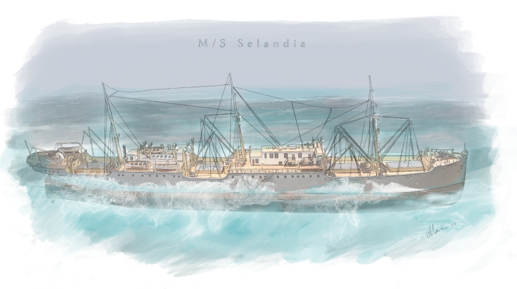
In 1912, a ship sensation took place in the shipyard on Refshaleøen: The new build no. 276, M/S Selandia saw the light of day. M/S Selandia was the first diesel engine-powered ship to be approved to sail on the oceans.
The ship was created in a collaboration between B&W and ØK, who saw the diesel engine as an effective replacement for the steam engine as propulsion engine for ships. Effective because it had a better degree of efficiency, needed less space for fuel and less manpower, saving space in the engine room.
Selandia was built at the B&W shipyard on Refshale Island and completed a successful trial voyage in the ice-filled Øresund in February 1912. The ship was handed over to EAC on 17 February and subsequently set out on her maiden voyage on 22 February 1912 with Bangkok as the final destination. The ship had 900 tonnes of oil in a tank under the engine, so that there was enough fuel for both the outward journey and the return journey, as it was not then possible to refuel in Bangkok.
The ship caused a great stir all over the world and gave both EAC and B&W a commercial and technological edge over its competitors.
Selandia was thus the start of the phasing out of the steam engine as ship's propulsion machinery and laid the foundation for the success of the diesel engine in ships.
Selandia weighed approx. 7000 tons and could sail at a speed of 12-13 knots (20 km/h)
ENGINE FACTS – M/S SELANDIA
NO. OF MAIN ENGINES: Two eight-cylinder engines each with 1250 hp at 140 rpm
Performance: In total 2500 hp
Cylinder Diameter: 530 mm
Stroke length: 730 mm
Medium pressure: 5,3 bar
Starting air pressure: 20 bar
Compressed air atomization: at 60 bar
See also clips from the documentary "Magten over havet - M/S Selandia" (in english "Power over the sea - M/S Selandia"), which was shown in 2012 on the TV station DR K.
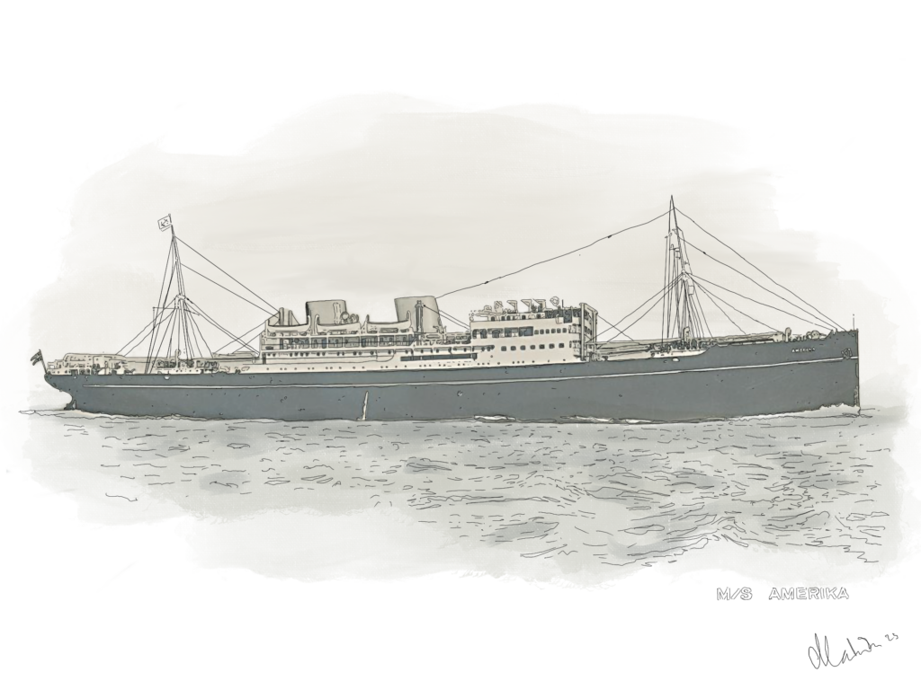
M/S AMERIKA
In 1930, B&W supplies its first two-stroke engine for B&W's newly built ship, the M/S Amerika. In fact, many of the new engines power B&W ships and the company thus benefits from the mutual production development of both ships and propulsion means.
The engine was pressurized atomized and received scavenging air from two separate electric fans. But M/S Amerika was a remarkable ship in several ways. Previously, many ships had no chimneys, while M/S Amerika had two. However the aft chimney functioned as a water tank.
The maiden voyage brought the ship from Copenhagen to Bangkok, but already on its second voyage, M/S Amerika sailed across the Pacific Ocean, as it did many times thereafter, until 1939.
Historically, the M/S Amerika was also a remarkable ship
In 1939, the M/S Amerika was en route from the Panama Canal to Los Angeles when World War II broke out. The ship continued its journey and returned towards Copenhagen. When the Germans occupied Denmark on April 9, the ship had reached the Faroe Islands. When the British occupied the Faroe Islands on 13 April, the British took ownership over the M/S Amerika and it subsequently served under the English flag. The majority of the Danish crew continued to serve on board and were trained as soldiers. The ship was painted gray and equipped with weapons.
In 1940, the ship loaded munitions and Red Cross ambulances in East Africa, but soon came to a hold at the cost of Malta for several months.
In 1941, a total of six ships stranded by Malta, were painted red and white striped to resemble Italian merchant ships, and on 23 July the ships set sail together under the Italian flag.
The waters between Sardinia and Tunisia were extremely dangerous, but the ships avoided both the many mines and three torpedoes from a German aircraft.
M/S Amerika reached Liverpool and after much-needed repairs, the ship once again carried cargo via the great oceans.
In 1942, M/S Amerika sailed in a convoy with 42 other merchant ships and 13 escort vessels. Between 20 and 25 April, the convoy was attacked by 19 German submarines.
On 21 April 1942, at 20:50, M/S Amerika was hit by two torpedoes from one of the German submarines and sank in just 30 minutes.
49 crew members, including 29 Danes, and 37 passengers lost their lives. Which is considered the greatest tragedy of the Danish merchant navy during the Second World War.
ENGINE FACTS - M/S AMERIKA
Build no.: 559
Ship and engine built by: Burmeister & Wain, Copenhagen
Build year: 1930
Client: The shipping company, Det Østasiatiske Kompagni A/S (The East Asian Company A/S)
Length: 141,73 m
Width: 18,90 m
Dept: 13,12 m
Type main engine: One B&W 662WF-140
Performance: 7000 hp
Speed: 14 knots
In DieselHouse you will find i.a. a model of the remarkable ship, M/S Amerika.
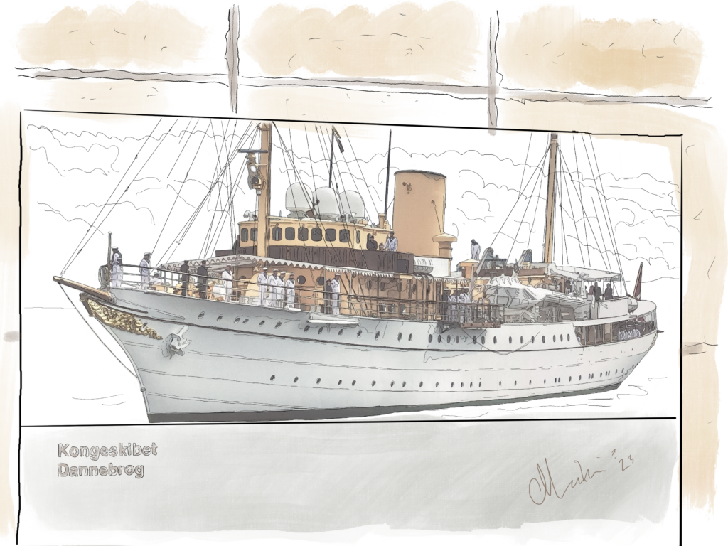
THE KING'S SHIP ENGINE
The royal ship Dannebrog was built at the Danish Navy's shipyard, Orlogsværftet on Holmen in Copenhagen in 1931. The ship was a replacement for the former Dannebrog, which was built by Burmeister & Wain in 1880. It was a paddle steamer. Dannebrog was handed over in the spring of 1932 to the Danish royal family, Christian X and Queen Alexandrine, who was also the ship's godmother. The ship was later inherited first by King Frederik IX and Queen Ingrid and later by Queen Margrethe II and Prince Henrik.
In 2020, Dannebrog had covered over 300,000 nautical miles on the royal family's summer cruises to Danish ports as well as trips to the Faroe Islands and Greenland, where the ship has been a regular part of the programme. The ship has a crew of 58 men + 27 people associated with the royal household.
Started weekly at the museum. See when below the section 'Opening hours'.
When Dannebrog was built, it was equipped with two main engines from Burmeister & Wain of the type 828VF, as well as two auxiliary engines of the type 222VHK.
These engines were replaced in 1955 with two B&W 828VF-50 main engines and three 320MTBS-30 auxiliary engines.
In 1980 these engines were replaced with two B&W Alpha main engines, type 6T23L-KVO a 870 HP at 800 rpm. Auxiliary engines type Scania DI12 62M. The replacement was carried out at Helsingør Shipyard.
The engine shown in the museum is one of the three B&W auxiliary motors for electricity production from 1955 and has the following data:
MOTOR FAKTA – KONGESKIBET DANNEBROG
Type:320MTBS-30
Number of cylinders: 3
Performance: 150 hp at 600 rpm
Weight: 10 tonnes
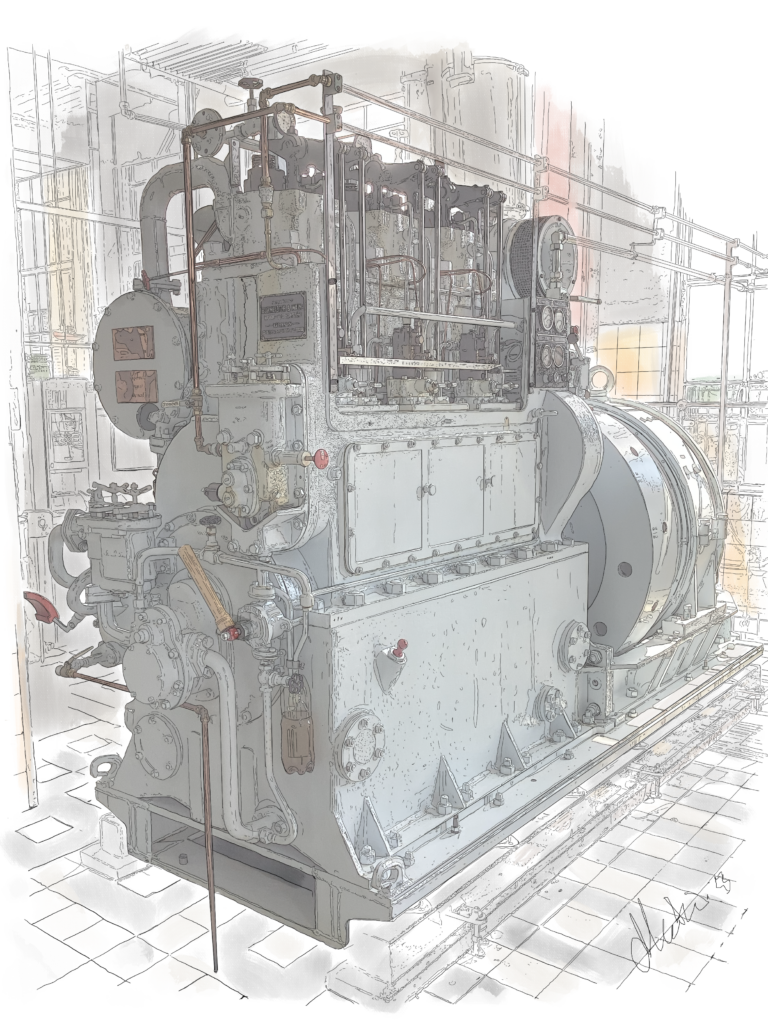
B&W2000
Also known as the H.C. Ørsted engine
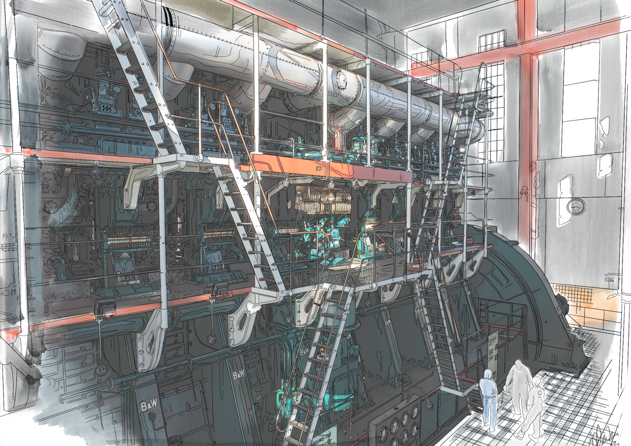
WOULD YOU LIKE TO FEEL WHAT 22,500 HORSEPOWERS FEELS LIKE?
Experience our giant diesel engine, B&W 2000, on the 1st and 3rd Sunday of each month at 11.00 (remember to check opening hours and when engines are started).
B&W 2000 is an eight cylindret, double-acting, longitudinally flushed two-stroke engine, with a bore of 840 mm and a stroke of 1500 mm. The engine was fitted with an alternating current generator, which was built by Swedish ASEA (today ABB). It was commissioned in 1933. The engine is 24.6 meters long, 12.5 meters high and weighs 1400 tons.
This mechanical marvel was built by B&W to produce power on the H.C. Ørsted works. It's purpose was to deliver electricity to Copenhagen twice a day, at peak strainage of the power grid (in the morning and at 3-4 p.m., when people got off work).
The diesel engine has the advantage over boiler-driven steam turbines that it can deliver power to the generator in just a few minutes and thus supply power when an urgent need arises. With its quick start-up, it was therefore better suited to equalize fluctuations in consumption than the large steam turbines that powered the rest of the plant.
The B&W 2000 was taken out of daily use in the late 60s, but engineers and machinists have carefully kept the engine ready to go until it was disconnected from the grid in 2004.
During World War II, the engine played an important role in the freedom fight, as the plant's own resistance group used it as a hiding place for weapons.
For more than 30 years, the engine was the world's largest diesel engine. Since 1970 and until 2004 the engine has functioned as an emergency system in the event of a power failure. That is why the machine has been tested once a month and ensured that there was always starting air pressure on the large starting air tanks.
This enabled the engine to deliver power, as Zealand and the South Sea Islands of Denmark was hit by a power failure in 2003. The engine started on compressed air and forced the towed pumps to deliver fuel and lubricating oil. For the first few minutes the engine ran without cooling water and then power was generated so that the cooling water pumps started.
The diesel engine is still functional but is no longer connected to the grid.
WHEN THE ENGINE IS STARTED
The diesel oil is injected into the cylinders with a pressure of approx. 350-400 atm. The purged air, which is necessary to clean the cylinder of combustion gases and supply fresh air, is provided by four pcs. gear blowers, which are pulled by the engine by means of a large chain. These deliver approximately 1,800 m3 of air per minute at an excess pressure of 0.25 atm.
The content of the lubricating oil tank is 40 tonnes, which approx. 10 times an hour is pressed through the bearings as lubricating oil and through the pistons as cooling oil with a pressure of 2.5 atm. The engine is fresh water-cooled in a closed system, and this water is kept cooled by water from the port of Copenhagen using a heat exchanger.
ENGINE FACTS - B&W2000 / H.C. ØRSTED ENGINE
Production name: DM 884WS-150
Production year: 1932
Type: double-acting, longitudinally flushed two-stroke engine
Performance: 22,500 ekh at 115 rpm (electric power on the generator 15 MW)
– Equivalent to 250,000 60W light bulbs
– Enough to light up 4,000 households
Cylinders eight
Cylinder diameter: 840 mm
Stroke length: 1500 mm
Starting air pressure: Approx 25 bar
Compression pressure: Approx 35 bar
Maximum pressure: Approx 50 bar
Medium pressure: Approx 7 bar
Consumption: 240 grams of fuel oil per kWh at 1200 kW = 2880 liters per hour
Dimension: 24,5 m long, 12,5 m tall
Engines total weight: 1400 tons
– Equivalent to 280 fully grown elephants
– 1,120 passenger cars (VW Passat)
– or 18,000 people of average size
Of this, a complete cylinder of 20 tonnes, crankshaft 140 tonnes and generator rotor 80 tonnes.
Total number of operating hours: about 75,000 hours
The engine is demonstrated to the public twice a month, first and third Sunday of the month, as well as on special occasions (e.g. Culture Night). See when below the section 'Opening hours'.
BUR-WAIN

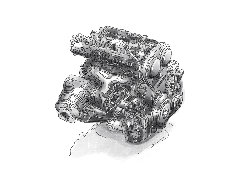
BUR-WAIN 6A 13D DIESEL ENGINE FROM 1945
Bur-Wain dieselmotorerne blev produceret i årene 1938-1956 hos B&W på Wilders Plads. I alt blev der produceret ca. 21.000 enheder af denne type motor.
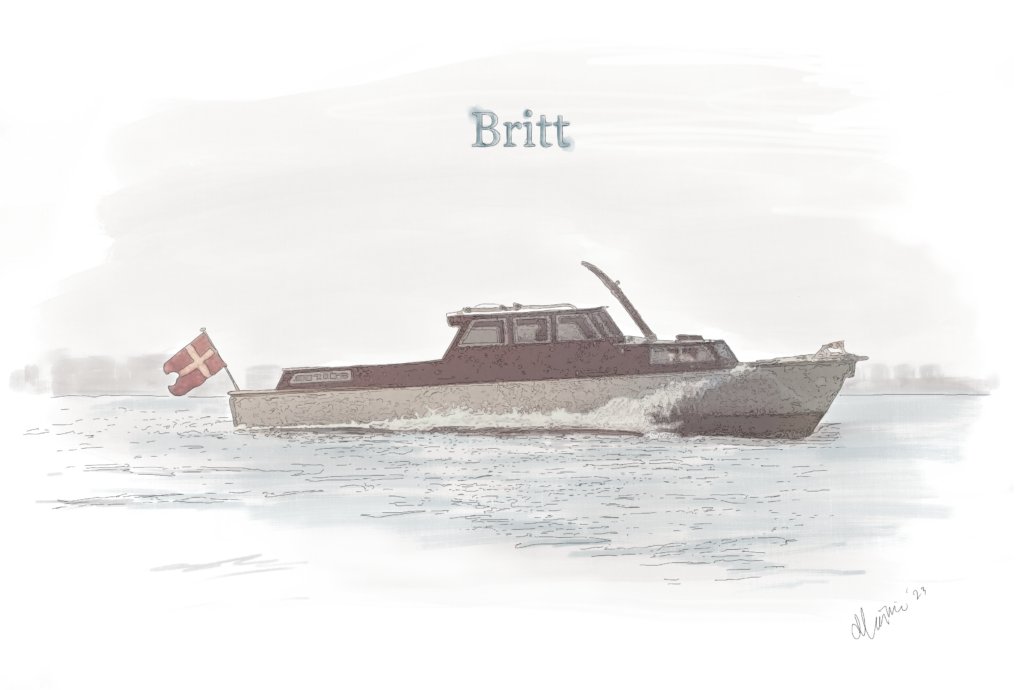
The Bur-Wain engines were primarily used in trucks and buses, but were also used for shunting locomotives for DSB and for smaller boats.
The exhibited engine has been in the motorboat "Britt" and the owner Ib Petersen has built the engine from spare parts in the period 1995-1997. A few years ago, Ib Petersen donated the engine to DieselHouse and present it weekly to the audience.
ENGINE FACTS – BUR-WAIN
Type: Bur-Wain Diesel 6 A 13 D four-stroke engine with direct fuel injection
Year: 1945
Cylinders: Six
Cylinder diameter: 110 mm
Stroke length: 135
Slagvolumen: 7,7 liters
Compression: 17:1
Performance: 105 ehk at 2000 rev/min
Max omdrejningsmoment: 588 Newton meters (Nm) at 1500 rpm
Started weekly at the museum. See times for motor starters under the section 'Opening hours'.
THE DIESEL ENGINE IN A HISTORICAL PERSPECTIVE
Since the first experimental engine Diesel produced, there has been an incredible development in engines, but also in the processes of the engines. This development has meant that diesel engines today are the all-dominant main engine in ships and in many large and small electricity plants, especially on islands around the world.
Diesel and B&W's test engines are designed as four-stroke engines and B&W continues for more than 25 years to adhere to the four-stroke principle. Diesel engines are quickly becoming leaders in all areas where engine power is needed and B&W is gaining more and more competitors, both within stationary engines and marine engines.
In fact, many of the new engines power B&W ships and the company thus benefits from the mutual production development of both ships and propulsion. However, there are competitors who have successfully developed the two-stroke diesel engine, which is simpler and more efficiently constructed.
B&W's engineers responded by developing a double-acting four-stroke engine that further increases the engine's performance.
In 1930, B&W finally delivers its first two-stroke engine to the newly built ship, M/S Amerika. During the development work with the two-stroke engine, B&W runs into problems with the flushing principle used by the competitors, which turns out to be a decisive advantage for B&W's two-stroke engine, as the solution becomes the longitudinal flushing principle, which is significantly more efficient and which is patented. B&W's longitudinally flushed two-stroke engine will be offered in the coming years in several variants of single-acting/double-acting, opposed piston, crosshead engines and trunk engines.
In 1939, significant investment was made in the single-acting cross-head engine with exhaust valve. It turns out to be the right choice, as the relatively simple construction in the coming years turns out to contain the development potential that can satisfy the future requirements in the shipping industry.
In 1951, the main objective was to achieve higher speed. And so B&W introduced the B&W two-stroke engines with turbochargers, which increase performance by 35% and made the engines both smaller in size and weight.
In 1973, the oil crisis puts the focus on fuel consumption, which represents an ever-increasing operating cost of, among other things, ships, from about 20% in 1972 to 50% ten years later. Here it turns out that the long-stroke engine is the solution and in this context longitudinal flushing is the optimal principle.
Meanwhile, it became increasingly difficult throughout the 20th century for industrial production to survive in Western European countries, where wages and production costs significantly exceed the level in Eastern Europe and Asia. In 1950, 65% of production licensees were European (today 100% are Asian).
From 1979, MAN buys 50% of the B&W shares, then a further 49% and finally the remaining.
The focus was now on the intelligent engine, which is controlled electronically, which ensures more stable operation and an improved control of fuel consumption and emission of environmentally harmful substances.
TODAY
Which leads us today, where development has continued on to reaching new goals.
Read more about the new goals and innovations on man-es.com
HOW THE DIESEL ENGINE WORKS
The diesel engine is a combustion engine that works by self-igniting fuel. In the four-stroke diesel engine, air is sucked in or pressurized, while in the two-stroke engine only air is pressurized, which is compressed and compresses the molecules, causing the temperature and pressure to rise so much that the fuel, the diesel oil, that is injected self-ignites. This happens just before the piston reaches the top position. During combustion, the temperature and pressure in the cylinder rise further, so that the piston is pressed back and provides mechanical work to the crankshaft.
The diesel engine is used both as a stationary power machine and for propulsion of ships, trains and cars.
The diesel process is characterized by the cylinder being filled with clean air, which is compressed by the movement of the piston to a pressure of up to 150 bar and a maximum temperature of 750°C. Shortly before TDP (top dead center), the diesel oil is injected, which self-ignites due to the high temperature. The combustion results in a pressure increase of up to 200 bar and a maximum temperature of up to 1,750°C. Combustion continues at the high pressure until it is completely finished at approx. 5-15 °KV after TDP.
FOUR-STROKE ENGINE
The cycle of the four-stroke engine is divided into four strokes; intake, compression, expansion and exhaust.
TWO-STROKE ENGINE
In the two-stroke engine, combustion takes place every time the main piston is in the top position. Flushing and exhaust are controlled either exclusively by flush ports (transverse flush/reverse flush), or by flush ports and exhaust valve (longitudinal flush).
To-taktsmotoren har tiltalt mange bilkonstruktører pga. sin enkelhed, men trods brug af forskellige tiltag er det ikke lykkedes at styre indsugning og udblæsning så godt, at motoren kan måle sig med fire-taktsmotoren i f.t. effektiv forbrænding. To-taktssystemet er udbredt blandt skibsdieselmotorer.
TURBOCHARGER
Da mængden af brændstof, der kan forbrændes i en dieselmotor, er afhængig af luftmængden i cylinderen, kan ydelsen hæves ved, at luftmængden har et højere tryk uden samtidig at have højere temperatur. Det gøres ved at komprimere skylleluften enten i en mekanisk drevet blæser eller i en turboblæser (også kaldet en turbolader).
Turbochargers are used for ship engines as well as for the smaller diesel engines used in ships for electricity production (auxiliary engines). They are also used for diesel engines in construction equipment as well as in buses, trucks and cars.
DOUBLE ACTING
When an engine is double-acting, you can bring the engine to combustion twice per round, instead of one. When the piston is in the top position, as well as in the bottom position.
This is particularly effective on large engines such as the B&W 2000, also known as The H.C. Ørsted Engine, here at the museum.
Det fungerer således, at cylinderen er meget lang, med et topstykke (cylinderdæksel) i begge ender af cylinderen og skylleporte midt på cylinderen. En stempelstang forbinder stemplet med et krydshoved uden for cylinderen, hvortil plejlstangen er tilkoblet. En pakdåse tætner omkring stempelstangen ved gennemgangen af det nedre cylinderdæksel.
LONGITUDINAL RINSING
Means that the fresh air enters when the piston is at the bottom and pushes the combustion gas out through a valve at the top of the cylinder.
THE PETROL ENGINE
The gasoline engine is characterized by the fact that a mixture of atomized and vaporized gasoline and air is compressed and ignited via en elektrisk dannet gnist. This is also called the Otto process.
Otto processen anvendes både i fire- og to-takts motorer. Blanding af brændstof og luft sker enten i en karburator eller ved indsprøjtning og forstøvning i enten indsugningsmanifolden eller, som i den seneste motorudvikling, direkte i forbrændingsrummet. Otto-processen anvendes altovervejende i stempelmotorer svarende til dieselmotoren, men processen er også anvendt i Wankelmotoren (en varmekraftmaskine med intern forbrænding, hvor stemplet, sammenlignet med Ottomotoren, er erstattet af en trekantet rotor. Konstrueret 1953 af tyskeren Felix Wankel (1902-1988)). I lighed med dieselmotoren er det muligt at anvende turboladning af forbrændingsluften.
Shortly before the pressure is up to 40-50 bar and the temperature reaches 2200-2500 °C, this point is also called TDP (top dead point), the fuel is ignited via an electric spark. A small explosion occurs which pushes the piston back which causes the shaft in the motor to rotate.
When the piston is pushed away from the top of the cylinders, there is again room for fresh air in the cylinder, air ducts open and let the hot air out, while cold air is taken in and cools the engine. Waste gases, primarily carbon dioxide and water, are expelled via the exhaust pipe.
DIFFERENCES IN THE PETROL ENGINE,
AGAINST THE DIESEL ENGINE
In several aspects, the engines differ from each other.
Differences in the structure of the engine
The main difference is the use of spark plugs in the compression chamber which is necessary to ignite the fuel/air mixture in the petrol engine.
Differences in compression
The compression ratio in a diesel engine is significantly higher than in a petrol engine. This is a necessity in order to achieve a sufficiently high temperature to self-ignite the fuel. On the other hand, a lower compression ratio is necessary in the petrol engine to avoid self-ignition before the desired ignition time. The compression in the diesel engine is 14:1 to 25:1, compared to the petrol engine where it is 8:1 to 12:1.
Differences in fuel/air mixture
In the diesel engine, it is necessary for a complete combustion to have sufficient air. Excess air has no significant influence on the combustion, but is beneficial as the air has a cooling effect on the combustion chamber components.
In the traditional petrol engine, on the other hand, it is essential to have a stoichiometric forhold mellem benzin og luft for at opnå en optimal forbrænding (støkiometri, er læren om de mængdeforhold, hvorunder de kemiske grundstoffer og forbindelser reagerer med hinanden, herunder altså luft og brændstof).
The combustion temperature is generally higher in the diesel engine, due to the high compression, while the exhaust temperature is typically lower in the diesel engine, because of the greater expansion.
Lean Burn
Motorer udvikles hele tiden og noget af det seneste indenfor støkiometrisk optimering, forgår ved direkte indsprøjtning i forbrændingsrummet og avancerede indsprøjtningsteknikker opnår et støkiometrisk forhold omkring tændrøret, mens den resterende forbrænding foregår med luftunderskud (lean burning), som giver en lavere forbrændingstemperatur og dermed færre NOx’er. Denne type motor kaldes også en mager-mix motor, fordi luft/brændstof-blandingen holdes på et magert niveau.
ELECTRICITY PRODUCTION & ITS USE
H.C. Ørsted and electromagnetism
On 21 July 1820, H. C. Ørsted published the very first scientific article describing electromagnetism.
Electricity and magnetism have been known far back in history, but have always been seen as two completely independent areas. H.C. Ørsted changed all that.
He had observed electric current through a platinum wire, affecting a compass needle.
After several experiments, he was able to establish that both electricity and magnetism are created by moving electrons. Electricity by electrons moving through a wire and magnetism when the electrons move in the same direction. So when his compass needle made small jerks, in the presence of the current carried through the platinum wire, as in a wire, it is due to the discovery of the electromagnetic field.Electromagnetism was born.
Electromagnetism is the basis of everything from wind turbines to mobile phones and other electric motors for e.g. cars.
Electricity produktion
Production of electricity on a larger scale takes place predominantly by converting mechanical energy into electrical energy. The mechanical energy is mainly produced by wind and water power, water vapor and combustion processes
that drive wind, water and steam turbines as well as gas turbines and engines that are connected to power generators. In addition, electricity production with solar cells has grown to a significant part of electricity consumption in recent decades. On a smaller scale, fuel cells are used today which convert hydrogen into electricity.
Direct current and alternating current generators
Both types of generators come into play largely at the same time in connection with the electricity supply to the public at the end of the 18th century. The public networks today exclusively supply alternating current, while direct current dominates in all forms of electronics. In both cases, the technology is based on electromagnetism, where an external force is converted into electric current.
The principle is illustrated in the attached sketches, which show a rotating armature with an armature winding in a magnetic field, whereby a current is generated in the winding. Each time the winding is perpendicular to the magnetic field changes current direction in the winding. In the alternating current generator, the conductor in the armature winding is connected to two slip rings and the carbon brushes therefore deliver alternating current from the slip rings.
(Sketch coming)
The direct current generator is equipped with a single two-part slip ring (commutator) where the conductor of the armature winding is connected to each half of the slip ring. The carbon brushes, which are offset by 180 degrees, change sliding half when the armature winding is perpendicular to the magnetic field. The two-part slip ring causes the carbon brushes to deliver a pulsating direct current. By going from two commutator segments to a larger number of segments and a corresponding number of windings which are evenly distributed on the rotor, an approximately constant direct current is achieved.
The electric car
The very first electric-powered car saw the light of day as early as 1832 and was built by the British inventor, Robert Anderson. But it wasn't until the second half of the 19th century before the electric car was made practical.
In 2023, it is believed that there will be 26 million electric cars on the world's roads, which is 60% more than in 2021 and a number that is expected to increase further in the coming years.
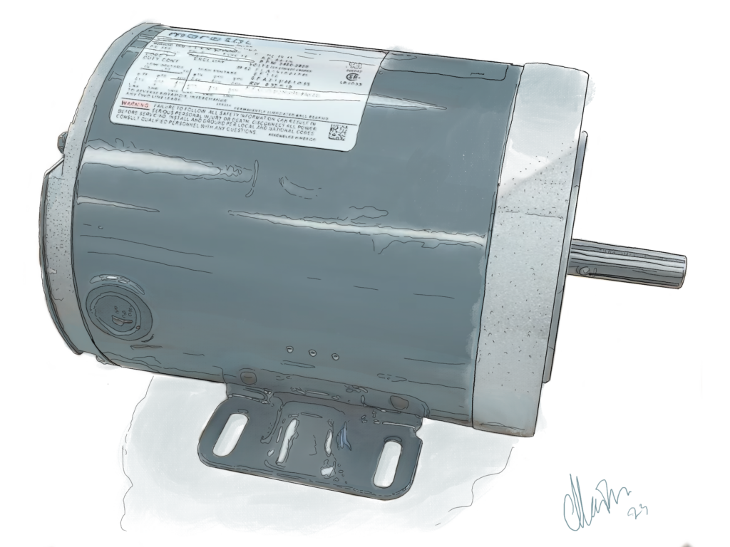
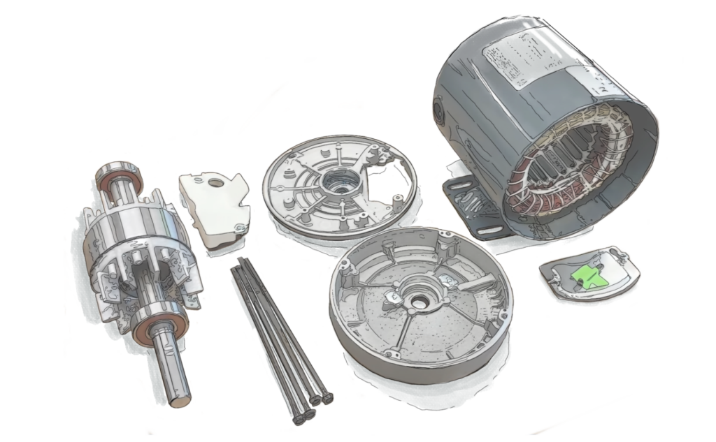
The electric engine
Electric engines are today a very common and fairly simple motor. They also come in several shades and can look different. Often they don't look like anything special and rarely consist of as many parts as other engines.
What electric motors have in common is that they convert electrical energy into mechanical energy.
This happens by the electric engine receiving energy from e.g. a battery through wires. The electrical energy energizes copper wires inside the electric engine, which via electromagnetism causes a rotor to turn, on the rotor is mounted a shaft that goes through the engine and out at the opposite end. The shaft rotates together with the rotor. At the end of the electric engine's shaft, the device that must receive the mechanical energy is placed.
Source: Den Store Danske (the Danish Dictionary) and Videnskab.dk (science . dk)
ELECTRONIC ENGINE MANAGEMENT (EMS)
In the early 1980s, a groundbreaking advancement in engine control took place with the introduction of Electronic Engine Management (EMS). This technology evolved in response to increasingly stringent vehicle emission regulations, particularly in California, where the harmful health effects of air pollution created a demand for cleaner and more efficient engines. At the same time, the rising oil prices of the 1970s made fuel savings an economic necessity, further driving development.
However, the real technological leap was not solely based on electronics but rather on the transition from mechanical to electromechanical (mechatronic) control of fuel injection and valve timing. Previously, these functions were directly linked to the crankshaft via chain drives and camshafts, limiting the flexibility of the engine’s combustion cycle. The development of microchips and sensors enabled the implementation of computer-based engine control, revolutionizing combustion process management. With EMS, the combustion process could be controlled far more precisely and flexibly, leading to significantly improved efficiency and lower emissions across the engine's entire operating range.
The technology expanded into the marine and energy sectors in the 1990s as a response to emission regulations, initially in various regions but also in anticipation of future regional and global maritime emission standards.
Early electronic systems measured only a few parameters, such as engine speed and air-fuel mixture. However, modern EMS systems in large engines now monitor hundreds of data points—from cylinder pressure to NOx and SOx levels in exhaust gases. This precise control has improved engine efficiency by up to 30%, significantly reducing both fuel consumption and emissions.
Mechatronic control of marine engines also serves as a platform for developing engines capable of running on alternative fuels such as LNG, methanol, and ammonia, which reduce CO₂ emissions—critical steps toward achieving climate-neutral shipping.

Billedtekst: ME Engine Control System – Main principles
For machinery and engine design, this development has meant that traditional mechanical expertise has been supplemented with knowledge in software and electronics to optimize and maintain engine management systems.
WHAT IS POWER-TO-X?
WHY POWER-TO-X?
When we talk about Power-to-X (PtX), it opens up a wide range of issues that we, as a society, would like to solve: getting rid of fossil fuels, meeting an increasing need for energy, converting what we have too much of (e.g. CO2) to a resource (energy), safe storage of e.g. CO2, longer storage of power from renewable energy, such as solar and wind.
But what does Power-to-X actually cover?
Power-to-X means: converting electricity (power) into something else (x).
Electricity can, for example, be converted via electrolysis into hydrogen, which can either be used directly or combined with other elements and refined into e.g. fuel, gas and chemicals.
How does Power-to-X work?
We receive power (electricity), from e.g. wind or solar energy. Via electrolysis, water (H2O) is split into (H2) hydrogen and (O) oxygen.
The hydrogen can either be used alone, or be converted into ammonia, methanol or methane by adding nitrogen (N) or carbon (C) from CO2. These are also called e-fuels or electro-fuels because electrolysis has been used to produce them.
E-fuels can be broken down into three groups: Power-to-Gas (PtG), Power-to-Liquid (PtL) and Power-to-Chemicals (PtC):
Power-to-Gas
Synthetic natural gas (SNG) can be used directly in the existing gas infrastructure without changing anything else.
Renewable energy is used to run an electrolysis plant that breaks down water into hydrogen and oxygen. This results in hydrogen that can be added to the natural gas grid or used as fuel for other applications. Alternatively, carbon dioxide can be added to the hydrogen in a methanation reactor, resulting in synthetic methane, also known as SNG or e-gas. CNG can be stored and used directly as a fuel for mobility or heating purposes.
Power-to-Liquid
Hydrogen is converted into methanol, which can be used in the production of synthetic fuels for road and air transport. It can be used directly by the mobility sector and the existing petrol or diesel infrastructure.
PtL can be used for fueling planes, trucks and ships.
Power-to-Chemicals
By combining hydrogen with CO2, nitrogen or other compounds, a chemical reaction is triggered and chemicals such as ammonia, ethylene or propylene are produced, which can be used in industries to produce various products.

So why isn't the whole world running on e-fuels already?
At DTU (the Danish Technical University), Professor of Physics, Jakob Kibsgaard describes that: "At the moment, the conversion of electricity to hydrogen is the most used power-to-x process. It is a well-known process that we can implement on a large scale. However, the process remains both expensive and energy-intensive. One third of the energy in the electricity used for the electrolysis process is lost. Thus, hydrogen contains only two thirds of the energy used to produce it.
"Although we are able to develop hydrogen fairly efficiently, the number of places we can use hydrogen is limited. For example, it is not suitable for heavy transport or in industries. Therefore, it is necessary to process the hydrogen further in a synthesis process”.
At DTU, research is being carried out to produce e.g. methanol or kerosene, without first producing hydrogen, to make the process more efficient.
In order for Power-to-X to succeed, Jakob Kibsgaard predicts that more efficient catalysts are needed for the electrolysis process as well as a plan for integrating Power-to-X into the existing energy system.
MAN Energy Solutions built a Power-to-X plant for Audi in 2013
Audi's Power-to-X plant in Werlte, Germany, has now been taken over by kiwi AG. MAN delivered a complete PtX solution including a methanation reactor as a single source solution. The facility supplies natural gas, which is used for several purposes, including The ElbBlue container ship, which, as the first ship in the world, sails on synthetic fuel.
MAN power-to-X
On MAN-ES.com you can keep up with the latest innovations.
HYDROGEN AS A FUEL
Hydrogen is often referred to as one of the fuels of the future due to its potential to reduce CO2 emissions.
Hydrogen can be produced by electrolysis of water, where electricity splits water into oxygen and hydrogen, or via reforming of natural gas. Green hydrogen, which is produced only with renewable energy, is particularly promising as a sustainable energy source. Concrete examples of hydrogen's use are in fuel cells, which convert hydrogen into electricity with water as the only waste product, fuel for smelting furnaces in steel production, and fuel in combustion engines. Hydrogen as a fuel has been successfully tested at Mitsui in 2024 on a MAN-B&W 2-stroke test engine. Link to the article: World's First Successful Hydrogen Combustion Operation with a Large Marine Engine.
Udfordringerne inkluderer dog høje produktionsomkostninger for grøn brint og behovet for avancerede løsninger til transport og opbevaring. Brint er verdens mindste molekyle og så lille, at det nemt diffunderer gennem mange typer metaller, hvilket stiller enorme krav til motor fremstilling og transport. For at opbevare brint effektivt kræves specielt udformede beholdere, ofte lavet af avancerede materialer som kompositter eller belagt stål, for at forhindre lækager.
Hydrogen is typically stored and transported under very high pressure of 350-700 bar, or as liquid hydrogen at temperatures below -253°C. Liquid hydrogen requires vacuum-insulated containers, while transportation as a gas requires heavy-duty tanks and advanced logistics.
Explosions can occur at lower concentrations than many other fuels (4-75% in air), and therefore require strict safety measures at all stages of production, storage and use.

Illustration: Hydrogen combustion test on MAN B&W 4S50ME-T
If leaks occur, hydrogen can spread quickly into the air due to its low molecular weight. This can be dangerous, especially in confined spaces where hydrogen can form explosive mixtures. Safety systems such as sensors and valves are critical to detect and respond to leaks.
In 2022, global hydrogen production was around 90 million tonnes, but only around 1% of this production was made as green hydrogen. To meet global climate goals, green hydrogen production must increase significantly in the coming years. Hydrogen represents an opportunity for a greener future, but also a technological challenge that requires innovative solutions.
TIMELINE
The 19th century – the heyday of the steam engine
1712 - The Englishman – Thomas Newcomen invents the steam engine and James Watt improves the steam engine until the 1780s
1820 – H.C. Ørsted discovers electromagnetism
1832 – The Worlds 1st electric vehicle
1843 - H.H. Baumgarten starts a mechanical workshop in Købmagergade in Copenhagen
1846 - C.C. Burmeister joins H.H. Baumgarten
– En bred vifte af industrimaskiner produceres af B&B: Trykpresser, tørremaskiner og farvemøller
1865 - Baumgarten retires and W. Wain joins: Burmeister & Wain (B&W)
1881 – B&W's first milk centrifuge revolutionizes agriculture and wins Grand Prix at the World Exhibition in Paris in 1889
1892 – Rudolf Diesel patents his diesel engine
1896 - Rudolf Diesel has a stable diesel engine ready
1898 - B&W gets the rights to produce and further develop diesel engines
The 1900s – the heyday of the diesel engine
1904 - First diesel engine from B&W is delivered, B&W no. 1 to Niels Larsen's Vognfabrik in Frederiksberg. The engine drove a dynamo that ensured lighting for the factory.
B&W revolutionizes the engine market time and time again:
1910 - Holeby diesel engine no. 1 is ready and installed in Christoffersen's Power Station in Holeby on Lolland
1912 – The world's first diesel engine built for an ocean-going ship, M/S Selandia
1914-1918 - World War I
1920s - steamships are replaced by diesel-powered ships
1930 - B&W buys the competitor from Holeby on Lolland
1930 - B&W supplies their first two-stroke engine for the new built B&W ship M/S Amerika
1930s - B&W develops double-acting four-stroke engine
1932 – B&W 2000 står klar på H.C. Ørsted Værket. Motoren er tre etager høj og bygningen må bygges uden om motoren. I 30 år er motoren verdens største, indtil en B&W licenstager bygger noget endnu større
1939 – B&W concentrates its development around the single-acting two-stroke crosshead engine, hvilket muliggør grovere og billigere brændselsolie
1938 -1956 – omkring 21.000 Bur-Wain motorer produceres primært til lastbiler, busser og rangerlokomotiver
1939 – 1945 - World War II: weapons are hidden under the B&W 2000 engine by own resistance fighters. A coin from the war is still preserved under the engine.
1943 - B&W No. 1 is bought back
1951 - B&W introduces turbocharged two-stroke engine and increases performance by 35%, for faster propulsion, less weight and size
1950s - wages exceed production costs in Western countries and where 65% of licensees in 1950 are located in Europe, today 75% are located in Asia
1973 - Oil Crisis focus on better fuel economy
1979 - B&W becomes MAN og fortsætter innovation af ingeniørkunst indenfor motorer og står for mange af de motorer i skibe der krydser verdens have, lastbiler der leverer vores vare og busser der transporterer os. I ‘1979, MAN buys 50% of the B&W shares, then a further 49% and finally the remaining.
1980’erne – focus on design and production optimization, the engine factory in Christianshavn closes, production of key components and the test center is moved to Teglholmen while the head office moves to Avedøre Holme
1990's - The focus was now to build the intelligent engine, which would be controlled electronically ensure stable operation and an improved control of fuel consumption and emissions
1995-1997 – Ib Petersen bygger motor af reservedele fra Bur Wain motorer til sin båd Britt. Motoren udstilles senere på museet
2003 - The B&W 2000 engine from 1932 is used as an emergency power generator to start the electricity grid after a large power outage in the Øresund area, causing havoc in both Denmark and Southeren Sweden
2006 - B&W no. 1 is fully restored and ready to be started at the museum
2020s - MAN continues to innovate the market with new solutions Read more about the new goals and innovations on man-es.com
This page is continuously a subject to correction of eg. any errors.
All illustrations and animations on this page is by Maikie Andersen, Maikie.dk